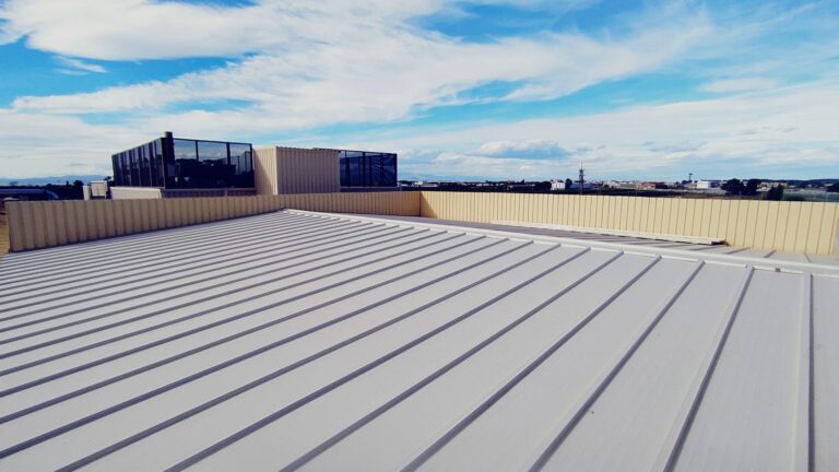
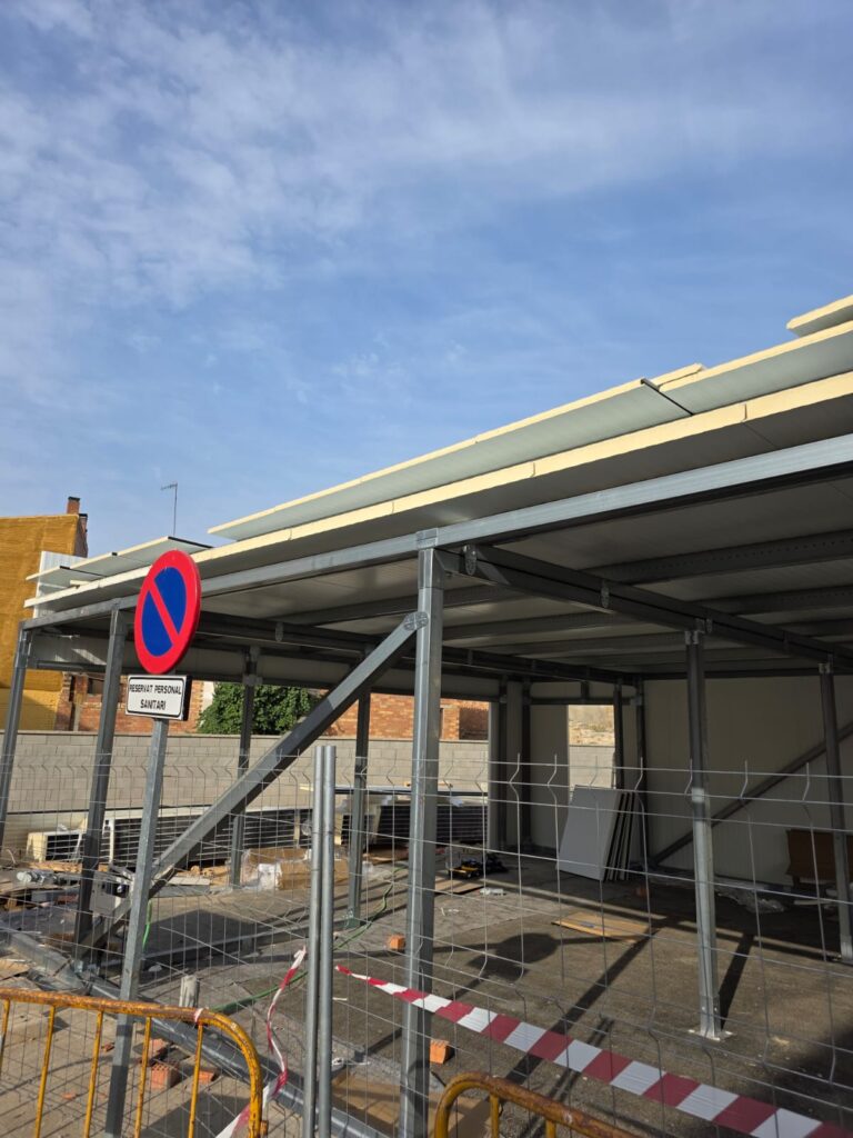
Tell us the panel type, area, thickness, location and whether you need supply only or installation. We’ll review the details to prepare a tailored proposal.
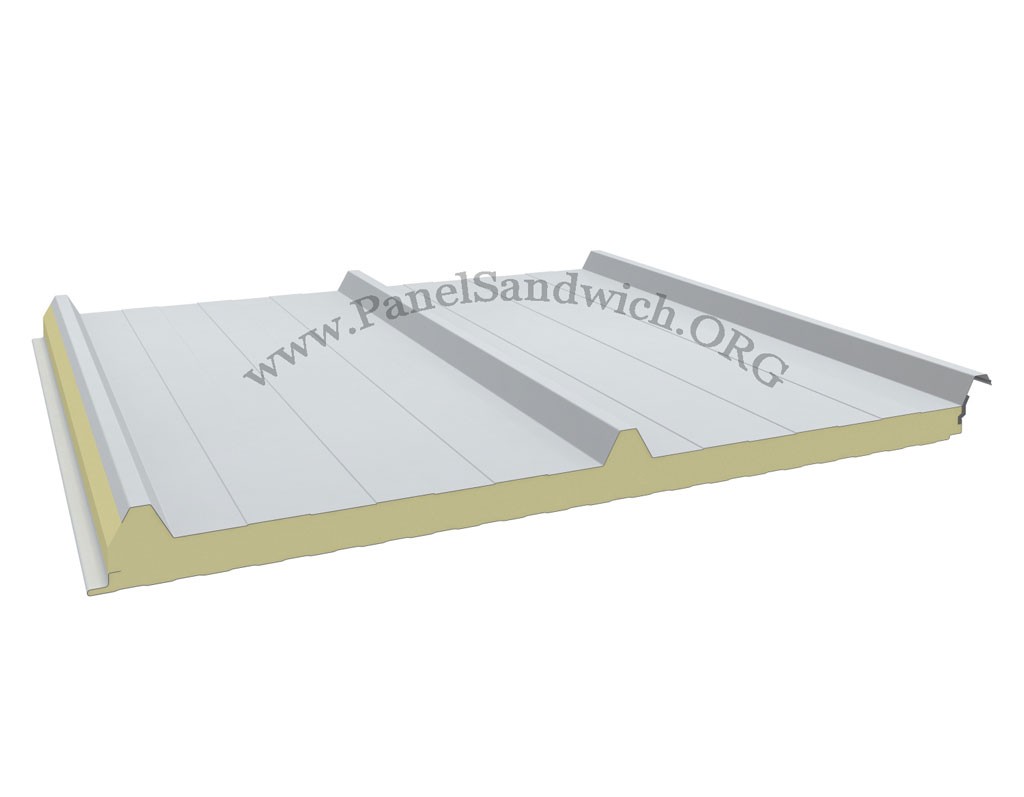
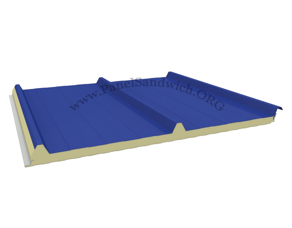
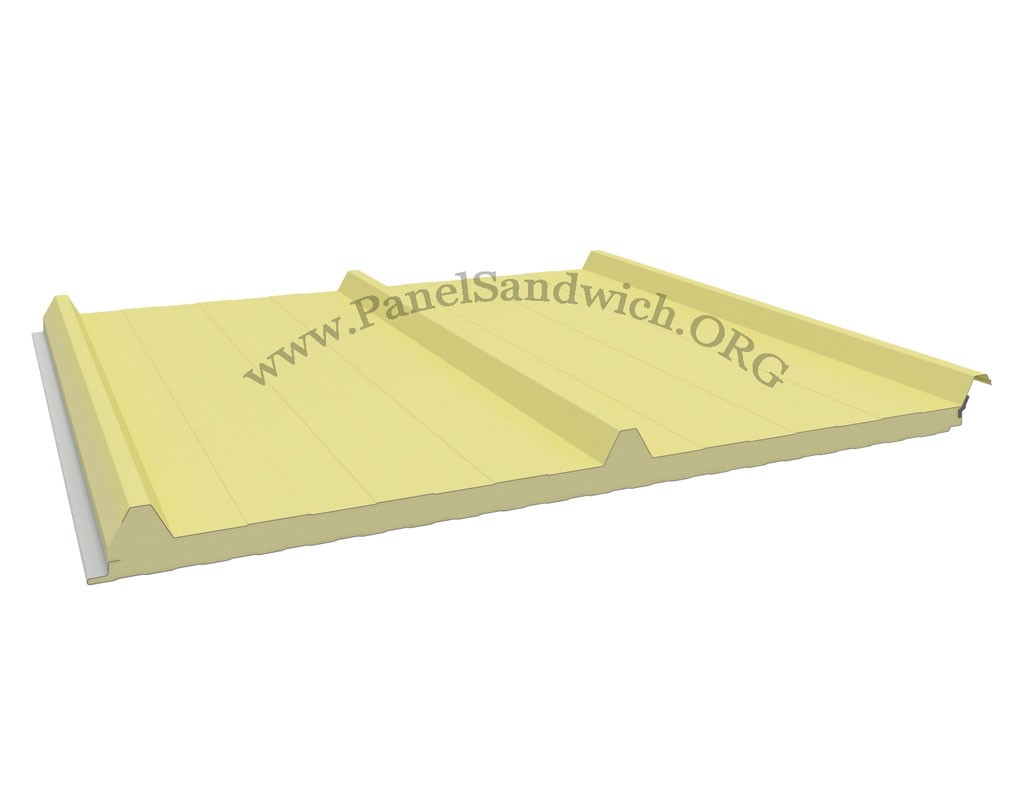
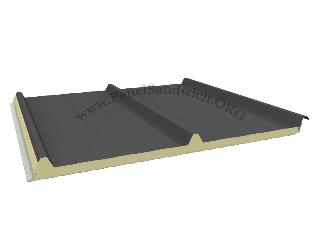
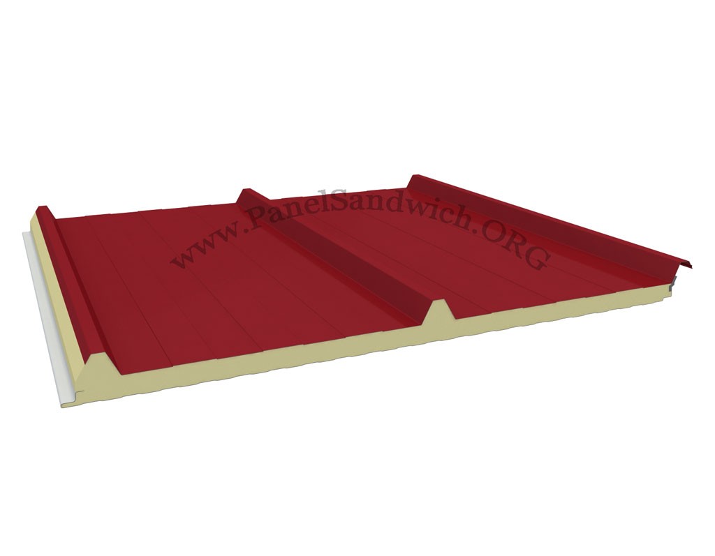
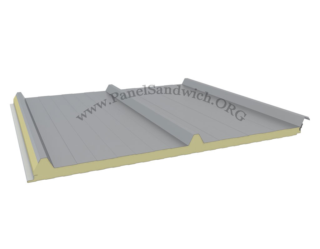
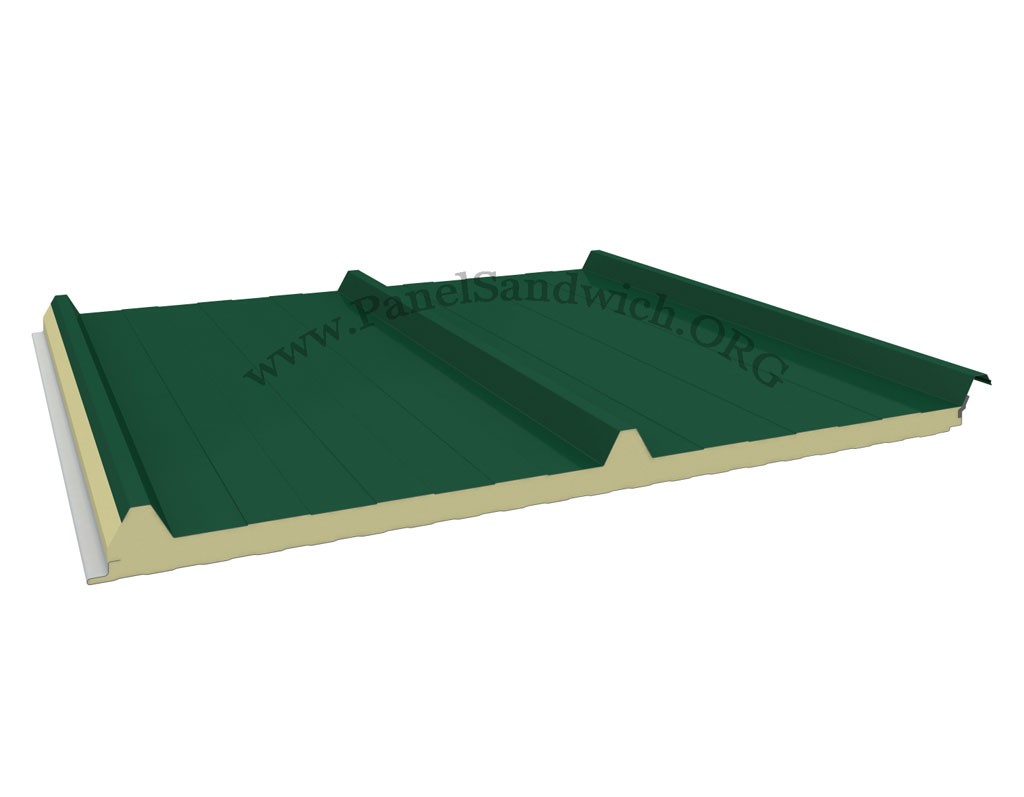
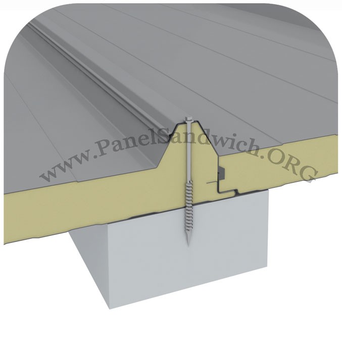
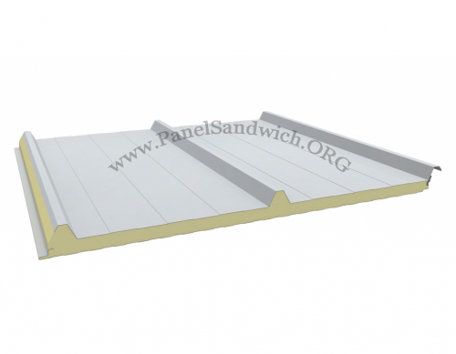
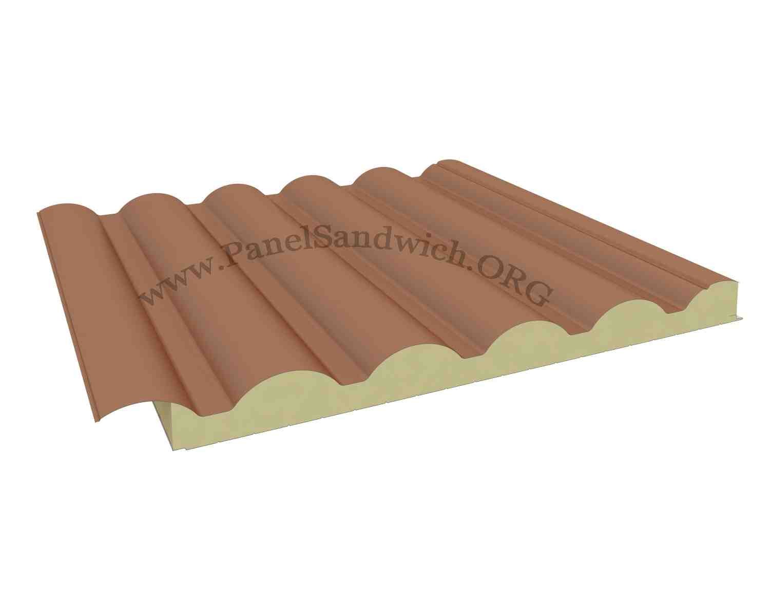
The 3-rib roof sandwich panel is an insulating solution for roofs and roof coverings, made up of two profiled metal sheets bonded to a rigid polyurethane (PUR) or polyisocyanurate (PIR) core. Its three-rib geometry adds stiffness to the assembly and makes it possible to solve enclosure, insulation and exterior finish in a single prefabricated piece.
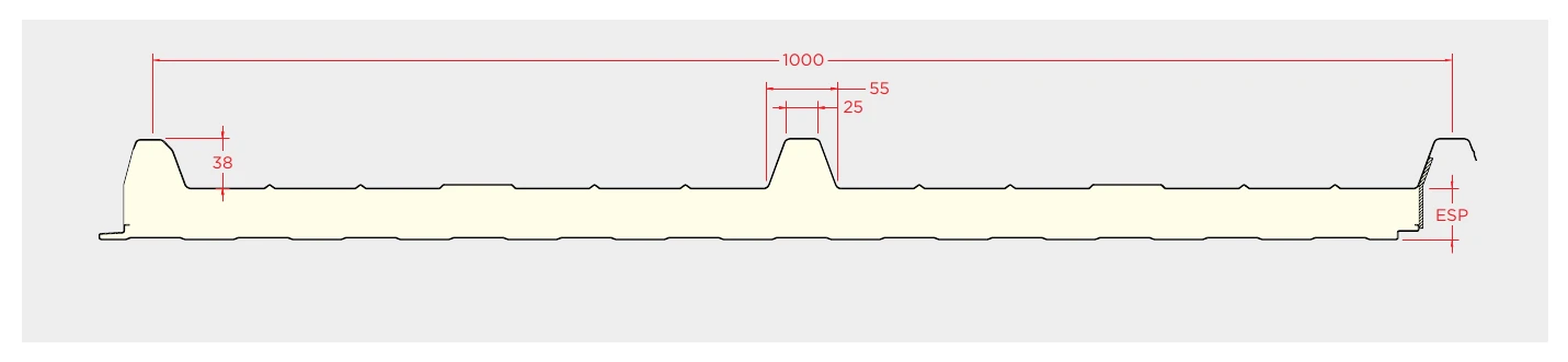
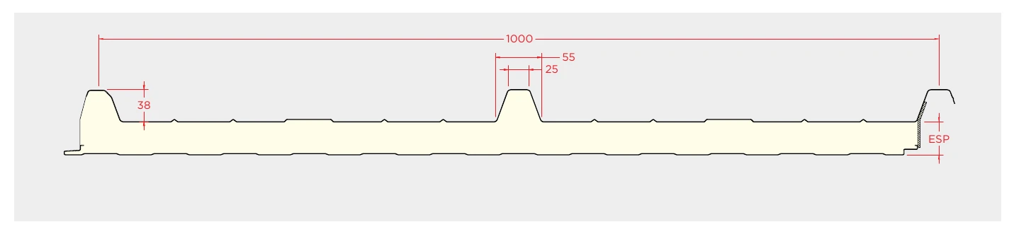
It has a useful width of 1,000 mm and is designed for roofs with a minimum slope of 5%. It can be used in industrial units, agricultural buildings, warehouses, porches, commercial roofs and other projects where a lightweight, insulating solution is required.
Manufactured in accordance with EN 14509. The insulating core has a declared thermal conductivity of 0.0207 W/m·K and a density of 40 kg/m³ ±10%.
Features
Application
Insulating panel intended for building roofs with a minimum slope of 5%. The choice of thickness, support spacing and sheet thickness must be checked in accordance with the actual loads and conditions of the project.
Dimensions
Thicknesses
30, 40, 50, 60, 80 and 100 mm ±2 mm
Greater thicknesses
120 and 150 mm ±2%
Useful width
1,000 mm ±2 mm
Manufacturing length
4.00–20.00 m ±10 mm
Recommended maximum length
13.00 m
Approx. rib height
38 mm
Metal facings
S250GD grade steel sheet to EN 10346.
Pre-painted coils with organic coating to EN 10169+A1.
Available sheet thicknesses: 0.4, 0.5 and 0.6 mm.
Insulating core
Polyurethane (PUR) or polyisocyanurate (PIR).
Thermal conductivity: 0.0207 W/m·K.
Density: 40 kg/m³ ±10%.
Reaction to fire PUR: B-s2,d0.
Reaction to fire PIR: B-s2,d0.
High fire-performance PIR option: B-s1,d0.
Coatings and colours
The standard finish is 25 µm polyester paint. Special, thicker coatings and 35 µm PVDF finishes can also be considered, subject to availability and supply conditions.
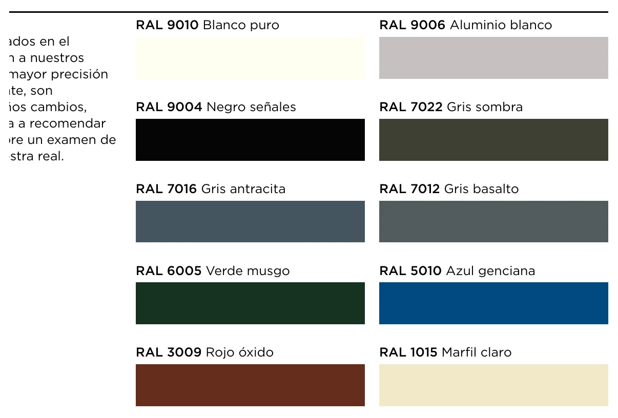
The range indicated in the technical documentation includes: RAL 9010, RAL 9006, RAL 9004, RAL 7022, RAL 7016, RAL 7012, RAL 6005, RAL 5010, RAL 3009 and RAL 1015.
Colours displayed on screen may vary from the actual finish. When the shade is critical, it’s worth checking a physical sample before confirming the order.
Installation
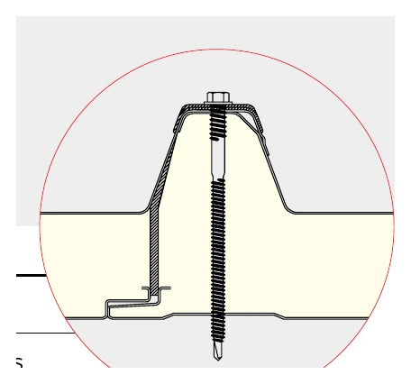
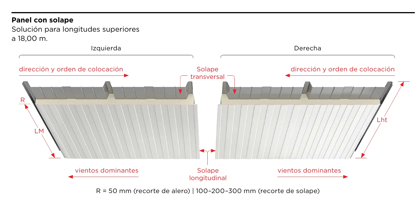
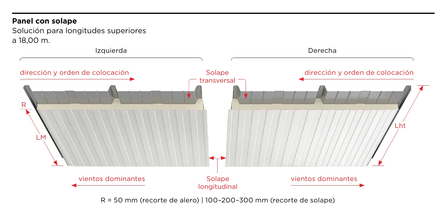
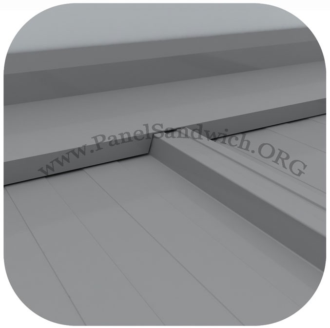
Installation of the 3-rib roof sandwich panel must be carried out on a correctly sized structure. Panels are laid respecting the installation direction, overlaps and the prevailing wind conditions expected for the roof.
For long roofs, a solution with transverse overlap can be used. The technical documentation considers this solution for lengths over 18.00 m and specifies overlap trims of 100, 200 or 300 mm. For the eaves trim, a 50 mm reference is indicated.
Maintain a minimum slope of 5%.
Install the panels following the planned installation order and direction.
Orient overlaps taking prevailing winds into account.
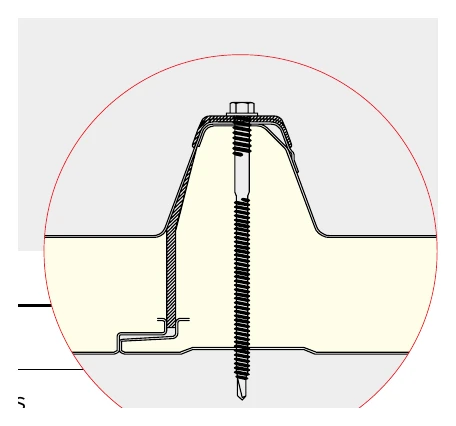
Size fixings and support spacing according to the project loads.
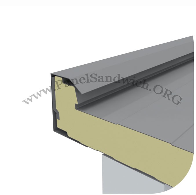
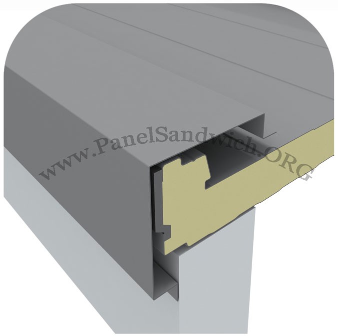
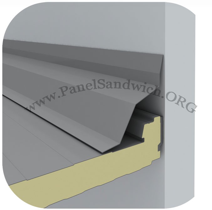
Correctly resolve ridges, sides, junctions, gutters and other flashings.
Important: a universal purlin spacing must not be set based solely on panel thickness.
DECLARED PERFORMANCE
Insulation, weight and technical data
Technical Data
Main characteristics
Configuration
3-rib insulated roof panel
Useful width
1,000 mm ±2 mm
Total thickness
30 / 40 / 50 / 60 / 80 / 100 / 120 / 150 mm
Steel sheet
S250GD · EN 10346
Sheet thicknesses
0.4 / 0.5 / 0.6 mm
Core
PUR or PIR
Core density
40 kg/m³ ±10%
Thermal conductivity
0.0207 W/m·K
Minimum slope
5%
Manufacturing standard
EN 14509
Thermal insulation and weight
Thickness
U-value
Weight 0.4/0.4
Weight 0.5/0.4
30 mm
0.62 W/m²·K
7.7 kg/m²
8.3 kg/m²
40 mm
0.47
8.1
8.7
50 mm
0.38
8.5
9.1
60 mm
0.32
8.9
9.5
80 mm
0.24
9.7
10.3
100 mm
0.20
10.5 kg/m²
11.1 kg/m²
120 mm
0.17
11.3
12.4
150 mm
0.13
12.6
13.6
Thermal insulation and weight
Thickness
U-value (W/m²·K)
Weight 0.4/0.4 (kg/m²)
Weight 0.5/0.4 (kg/m²)
30 mm
0.62
7.7
8.3
40 mm
0.47
8.1
8.7
50 mm
0.38
8.5
9.1
60 mm
0.32
8.9
9.5
80 mm
0.24
9.7
10.3
100 mm
0.20
10.5
11.1
120 mm
0.17
11.3
12.4
150 mm
0.13
12.6
13.6
Panel resistance by support spacing
The technical documentation includes uniformly distributed load tables for spans from 1.50 to 5.00 m, differentiating uplift and downward load, single or multiple support conditions, and 0.4/0.4 and 0.5/0.4 mm sheet configurations.
Panel selection must not be based solely on a generic table. Wind, snow, maintenance, suction loads, number of supports and the building configuration must be checked for each project.
View load tables · single span and multi-span
▲ Upward load▼ Downward loadValues in kN/m²“—” no published value for that span
Sheet 0.4/0.4 · single span
Swipe the table →
Thickness
Load
Permissible load (kN/m²) by distance between supports L (m)
1.50 m
1.75 m
2.00 m
2.25 m
2.50 m
2.75 m
3.00 m
3.25 m
3.50 m
3.75 m
4.00 m
4.25 m
4.50 m
4.75 m
5.00 m
30 mm
▲
1.84
1.46
1.20
1.00
0.85
0.73
0.63
0.56
0.47
0.39
0.31
—
—
—
—
▼
1.44
1.11
0.89
0.72
0.59
0.49
0.32
—
—
—
—
—
—
—
—
40 mm
▲
2.31
1.87
1.56
1.31
1.13
0.97
0.85
0.75
0.67
0.58
0.49
0.42
0.36
0.30
—
▼
1.80
1.44
1.17
0.96
0.80
0.67
0.57
0.39
—
—
—
—
—
—
—
50 mm
▲
2.80
2.31
1.95
1.66
1.43
1.25
1.10
0.97
0.87
0.78
0.68
0.58
0.50
0.44
0.38
▼
2.20
1.78
1.47
1.23
1.04
0.88
0.76
0.65
0.46
0.31
—
—
—
—
—
60 mm
▲
3.32
2.78
2.36
2.03
1.76
1.54
1.36
1.21
1.06
0.93
0.82
0.73
0.66
0.58
0.51
▼
2.60
2.15
1.79
1.51
1.29
1.11
0.96
0.83
0.71
0.52
0.37
—
—
—
—
80 mm
▲
4.40
3.75
3.23
2.81
2.46
2.13
1.79
1.52
1.32
1.15
1.02
0.91
0.81
0.73
0.67
▼
3.45
2.90
2.47
2.12
1.83
1.59
1.39
1.22
1.08
0.95
0.81
0.62
0.48
0.35
—
100 mm
▲
5.50
4.75
4.14
3.62
3.09
2.55
2.14
1.83
1.58
1.38
1.22
1.09
0.97
0.88
0.80
▼
4.32
3.69
3.17
2.75
2.40
2.10
1.84
1.63
1.45
1.29
1.15
1.03
0.87
0.69
0.55
120 mm
▲
6.63
5.67
4.93
4.36
3.62
2.98
2.51
2.14
1.85
1.62
1.43
1.27
1.14
1.03
0.94
▼
5.19
4.48
3.89
3.39
2.97
2.62
2.31
2.05
1.83
1.63
1.47
1.32
1.19
1.08
0.88
150 mm
▲
7.31
6.23
5.42
4.79
4.28
3.63
3.05
2.61
2.25
1.97
1.74
1.55
1.39
1.25
1.14
▼
6.53
5.70
4.99
4.39
3.87
3.43
3.04
2.71
2.43
2.18
1.96
1.77
1.60
1.46
1.33
Sheet 0.4/0.4 · multi-span
Swipe the table →
Thickness
Load
Permissible load (kN/m²) by distance between supports L (m)
1.50 m
1.75 m
2.00 m
2.25 m
2.50 m
2.75 m
3.00 m
3.25 m
3.50 m
3.75 m
4.00 m
4.25 m
4.50 m
4.75 m
5.00 m
30 mm
▲
1.60
1.21
0.95
0.78
0.65
0.56
0.49
0.43
0.39
0.35
0.32
—
—
—
—
▼
1.44
1.11
0.89
0.72
0.59
0.49
0.41
0.34
—
—
—
—
—
—
—
40 mm
▲
1.77
1.34
1.07
0.88
0.74
0.64
0.56
0.50
0.45
0.41
0.37
0.34
0.32
—
—
▼
1.80
1.44
1.17
0.96
0.80
0.67
0.57
0.49
0.42
0.36
—
—
—
—
—
50 mm
▲
1.94
1.49
1.19
0.98
0.83
0.72
0.64
0.57
0.51
0.47
0.43
0.40
0.37
0.35
0.33
▼
2.20
1.78
1.46
1.16
0.95
0.79
0.67
0.58
0.50
0.43
0.38
0.34
0.30
—
—
60 mm
▲
2.05
1.58
1.26
1.04
0.88
0.77
0.67
0.60
0.54
0.50
0.46
0.42
0.39
0.37
0.35
▼
2.60
1.96
1.53
1.23
1.01
0.85
0.72
0.62
0.54
0.47
0.42
0.37
0.33
0.30
—
80 mm
▲
2.41
1.82
1.46
1.21
1.04
0.91
0.82
0.74
0.68
0.63
0.59
0.55
0.52
0.50
0.47
▼
3.07
2.28
1.77
1.43
1.18
1.01
0.87
0.77
0.68
0.61
0.54
0.49
0.44
0.40
0.37
100 mm
▲
2.68
2.04
1.63
1.35
1.16
1.01
0.90
0.82
0.75
0.70
0.65
0.61
0.58
0.55
0.53
▼
3.32
2.48
1.92
1.55
1.28
1.08
0.94
0.82
0.73
0.65
0.58
0.53
0.48
0.44
0.40
120 mm
▲
2.90
2.23
1.79
1.49
1.28
1.13
1.01
0.92
0.84
0.78
0.73
0.69
0.66
0.63
0.61
▼
3.55
2.66
2.08
1.67
1.39
1.18
1.02
0.89
0.79
0.71
0.64
0.57
0.52
0.47
0.43
150 mm
▲
3.15
2.44
1.98
1.66
1.43
1.26
1.13
1.03
0.95
0.89
0.84
0.79
0.76
0.73
0.71
▼
3.79
2.86
2.24
1.81
1.50
1.28
1.10
0.97
0.86
0.77
0.69
0.62
0.56
0.51
0.46
Sheet 0.5/0.4 · single span
Swipe the table →
Thickness
Load
Permissible load (kN/m²) by distance between supports L (m)
1.50 m
1.75 m
2.00 m
2.25 m
2.50 m
2.75 m
3.00 m
3.25 m
3.50 m
3.75 m
4.00 m
4.25 m
4.50 m
4.75 m
5.00 m
30 mm
▲
2.07
1.64
1.34
1.12
0.95
0.82
0.71
0.62
0.51
0.42
0.34
—
—
—
—
▼
1.63
1.27
1.01
0.82
0.68
0.56
0.38
—
—
—
—
—
—
—
—
40 mm
▲
2.56
2.08
1.73
1.46
1.25
1.08
0.95
0.84
0.74
0.62
0.52
0.44
0.38
0.32
—
▼
2.02
1.61
1.31
1.08
0.91
0.77
0.65
0.45
0.30
—
—
—
—
—
—
50 mm
▲
3.08
2.54
2.14
1.83
1.58
1.38
1.22
1.08
0.96
0.84
0.73
0.62
0.53
0.46
0.41
▼
2.43
1.98
1.64
1.37
1.16
1.00
0.86
0.73
0.52
0.37
—
—
—
—
—
60 mm
▲
3.62
3.03
2.58
2.23
1.94
1.70
1.47
1.25
1.08
0.94
0.83
0.74
0.67
0.60
0.54
▼
2.86
2.36
1.98
1.68
1.44
1.24
1.08
0.94
0.79
0.59
0.43
0.30
—
—
—
80 mm
▲
4.75
4.06
3.51
3.06
2.63
2.16
1.81
1.54
1.33
1.16
1.03
0.91
0.82
0.74
0.67
▼
3.75
3.16
2.70
2.33
2.02
1.77
1.55
1.37
1.21
1.08
0.88
0.69
0.53
0.40
—
100 mm
▲
5.90
5.12
4.47
3.90
3.13
2.58
2.16
1.84
1.59
1.39
1.23
1.09
0.98
0.89
0.80
▼
4.66
3.99
3.46
3.01
2.64
2.32
2.05
1.82
1.62
1.45
1.30
1.16
0.94
0.76
0.60
120 mm
▲
6.82
5.83
5.09
4.51
3.65
3.01
2.53
2.16
1.86
1.63
1.44
1.28
1.15
1.04
0.94
▼
5.56
4.82
4.20
3.69
3.25
2.87
2.55
2.27
2.03
1.82
1.64
1.48
1.34
1.12
0.92
150 mm
▲
7.45
6.37
5.56
4.92
4.42
3.66
3.08
2.63
2.27
1.98
1.75
1.56
1.40
1.26
1.15
▼
6.96
6.10
5.38
4.76
4.22
3.76
3.35
3.00
2.70
2.43
2.19
1.99
1.81
1.65
1.50
Sheet 0.5/0.4 · multi-span
Swipe the table →
Thickness
Load
Permissible load (kN/m²) by distance between supports L (m)
1.50 m
1.75 m
2.00 m
2.25 m
2.50 m
2.75 m
3.00 m
3.25 m
3.50 m
3.75 m
4.00 m
4.25 m
4.50 m
4.75 m
5.00 m
30 mm
▲
1.88
1.42
1.11
0.91
0.76
0.65
0.56
0.50
0.45
0.40
0.37
0.34
0.31
—
—
▼
1.63
1.27
1.01
0.82
0.68
0.56
0.47
0.40
0.34
—
—
—
—
—
—
40 mm
▲
2.07
1.57
1.25
1.02
0.86
0.74
0.65
0.57
0.51
0.46
0.42
0.39
0.36
0.34
0.32
▼
2.02
1.61
1.31
1.08
0.91
0.77
0.65
0.56
0.49
0.42
0.37
0.32
—
—
—
50 mm
▲
2.28
1.74
1.39
1.14
0.97
0.83
0.73
0.65
0.59
0.53
0.49
0.45
0.42
0.39
0.37
▼
2.43
1.98
1.64
1.37
1.14
0.95
0.81
0.69
0.60
0.53
0.46
0.41
0.37
0.33
—
60 mm
▲
2.41
1.84
1.47
1.21
1.02
0.88
0.77
0.69
0.62
0.56
0.52
0.48
0.45
0.42
0.39
▼
2.86
2.33
1.82
1.46
1.20
1.01
0.86
0.75
0.65
0.57
0.51
0.45
0.40
0.36
0.33
80 mm
▲
2.84
2.13
1.69
1.40
1.20
1.05
0.93
0.84
0.77
0.71
0.66
0.62
0.59
0.56
0.53
▼
3.66
2.71
2.10
1.70
1.40
1.20
1.04
0.91
0.81
0.72
0.65
0.59
0.54
0.49
0.45
100 mm
▲
3.14
2.38
1.89
1.57
1.33
1.16
1.03
0.93
0.85
0.79
0.73
0.69
0.65
0.62
0.59
▼
3.94
2.95
2.29
1.84
1.53
1.29
1.11
0.98
0.87
0.78
0.70
0.63
0.58
0.53
0.49
120 mm
▲
3.40
2.61
2.09
1.73
1.48
1.30
1.16
1.05
0.96
0.89
0.83
0.79
0.75
0.71
0.68
▼
4.19
3.16
2.46
1.98
1.64
1.39
1.20
1.05
0.93
0.84
0.75
0.68
0.62
0.57
0.52
150 mm
▲
3.68
2.85
2.30
1.92
1.65
1.45
1.29
1.18
1.08
1.01
0.95
0.90
0.85
0.82
0.79
▼
4.47
3.39
2.66
2.15
1.78
1.51
1.30
1.15
1.02
0.91
0.82
0.74
0.68
0.62
0.56
TECHNICAL ADVICE
Which thickness do you need?
The data on this page (thicknesses, insulation, weights and load tables) are for guidance only. The right thickness depends on purlin spacing, roof pitch and the wind and snow loads in your area.
Tell us about your project and we will help you choose the thickness, supports and fixings for the 3-rib roof sandwich panel.
The minimum slope indicated in the technical documentation is 5%. The final design must also consider roof slope length, overlaps, flashings and the site’s climatic conditions.
The panel can be manufactured in 30, 40, 50, 60, 80, 100, 120 and 150 mm. Thicknesses from 30 to 100 mm have a stated tolerance of ±2 mm, while 120 and 150 mm have a tolerance of ±2%.
Both cores have a declared thermal conductivity of 0.0207 W/m·K. The documentation indicates reaction to fire B-s2,d0 for PUR and PIR, and B-s1,d0 for the high fire-performance PIR formulation.
The documentation considers manufacturing lengths between 4.00 and 20.00 m, although it sets 13.00 m as the recommended maximum length. For longer lengths, transport, handling and, where applicable, overlap solutions should be reviewed.