TECHNICAL INFORMATION · PRODUCTION
Sandwich panel manufacturing: production process
Sandwich panel manufacturing combines chemical dosing, forming of the metal faces, formation or incorporation of the core, pressing, curing, cutting, stacking, and packaging. The original technical page distinguishes between batch systems and continuous production lines.
This version preserves all the historical technical parameters of the original page, but expressly identifies the data that must be interpreted as process reference and not as universal performance of any current factory or panel.
Sandwich panel manufacturing principles
Manufacturing combines continuous materials—such as coil sheet—with a core that can be formed chemically during the line or incorporated as a rigid material previously produced. Process control seeks to maintain mixing, adhesion, geometry, and finish in a repeatable manner.
Polyol + polyisocyanate
Manufacturers receive liquid components and convert them into polyurethane through a controlled reaction, together with additives defined by formulation.
Precision and temperature
The viscosity and proportion of the components affect the mixture. For this reason, tanks, pumps, and control circuits are a critical part of the process.
Continuous or batch
Manufacturing can be carried out in closed molds per panel or in automatic lines where the panel is formed, cured, cut, and stacked continuously.
Materials and Finished Product
Beyond the process overview, it is useful to see how materials become the finished product and how geometry changes according to the application.

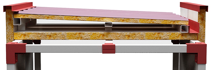
Panel Section
The final geometry integrates the two faces, the insulating core, and the joint formed during production.
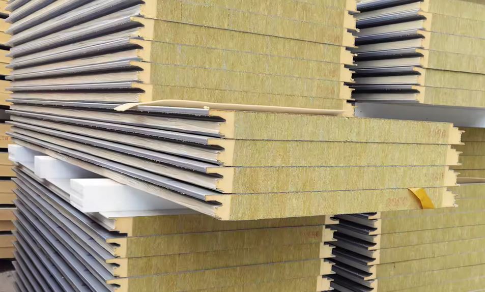
Finished and Stacked Panel
Edge finishing and package stability are important before transport.
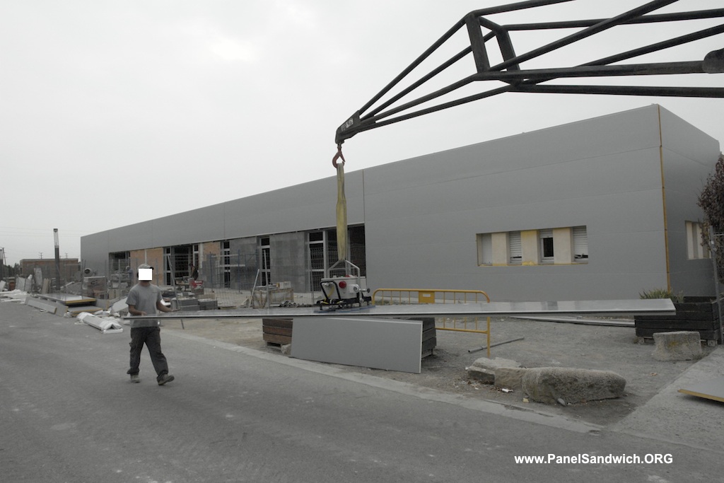
Product Handling
Length, rigidity, and surface finish determine the unloading and handling of the manufactured panel.
Reaction injection molding (RIM): dosing and mixing
The original page calls reaction injection molding (RIM) the process based on a high-pressure foaming unit. In this system, polyol, polyisocyanate, and additives are combined to generate a reactive mixture capable of forming microcellular or microporous foams in reduced cycle times.
Storage tanks and day tanks
The main components and additives—stabilizers, flame retardants, pigments, and others—are kept in storage tanks and transferred before production to feed tanks or day tanks.
Thermal control is important because a temperature variation, especially in polyols, modifies viscosity. The source describes double-walled tanks, with stirrer and temperature control circuits to maintain process conditions as constant as possible.
Recirculation before injection
Before each mixing and filling cycle, the components recirculate in the required proportions and at the required pressure. Electronically controlled actuators divert the flow from the recirculation circuit to the injection circuit and then restore recirculation.
Dosing pumps: precision, flow rate, and limitations
Dosing must be repeatable and precise. The objective of the pumps is to transport from the day tanks to the foaming head the correct quantity of each component, maintaining the intended mixing ratio.
The historical source cites flow rates of 12 to 150 liters per minute for axial piston pumps, highlighting their low noise level and precision. It also indicates two limitations: high-viscosity liquids and the presence of abrasive fillers.
| Element | Historical data | Function / limitation described |
|---|---|---|
| Dosing pumps | 12–150 L/min | The source cites axial piston pumps of high precision to reproduce mixing ratios. |
| Viscosity | Qualitative limitation | Axial piston pumps have limitations when liquids have high viscosities. |
| Abrasive fillers | Not recommended in the described configuration | The source warns that liquid components must not contain abrasive fillers for this pumping system. |
| Head nozzles | 100–150 m/s | Historical velocity cited for the components through the injection nozzles. |
High-pressure foaming head
The foaming head is the point at which the components meet and mix. The technique described uses high-pressure impingement: the liquids are injected into the mixing chamber and their kinetic energy promotes intimate mixing.
The original page cites component velocities in the nozzles of approximately 100–150 m/s.
Piston cycle and recirculation
- In recirculation position, the components return to the tanks through small ducts.
- When the piston is withdrawn, the mixing chamber opens and the components impinge on each other.
- When the piston advances again, mixing is interrupted.
- Recirculation is restored and the remaining reactive mixture is removed from the chamber.
This mechanism allows synchronization of mixture supply, especially in batch processes.
Production facilities and equipment
The system described integrates the mixing/injection machine, the mold or press, and the auxiliary equipment necessary to form, cut, and handle the panel.
| Equipment | Function within the system described |
|---|---|
| Feed tanks | Keep the components available under controlled thermal conditions. |
| Dosing / recirculation pumps | Control flow rate, proportion, and circulation prior to mixing. |
| Foaming head | Mixes the components by high-pressure injection. |
| Mold or press | Defines geometry and maintains the faces during expansion and hardening. |
| Auxiliary equipment | Profiling, heating, cutting, stacking, packaging, and automation according to line type. |
Batch system
Each panel is manufactured in a closed mold of the final dimensions.
- Allows more complex geometries.
- Can favor surface finish.
- Accepts alternative starting materials.
- Lower production rate.
Continuous system
The faces advance from coils and the panel is formed continuously.
- Oriented to large productions.
- Profiling, preheating, and foaming in-line.
- Double-belt press.
- Cutting, stacking, and packaging can be automated.
Batch production: mold molding
In mold molding, the panel is produced in a closed cavity whose dimensions correspond to those of the finished panel. The mold has a solid lower structure and a lid, and must withstand the pressures generated during foam solidification.
- The already profiled metal faces are placed inside the mold.
- The lower face rests on the bottom and the upper one is held in position by lateral supports.
- The lid is closed.
- An exact quantity of foam is introduced through a lateral nozzle; the source indicates that this operation lasts only a few seconds.
- After foaming, the panel remains in the mold approximately 40 minutes.
- The panel is removed and the mold is prepared for the next cycle.
Historical advantages cited: possibility of manufacturing complicated shapes, good exterior appearance, and use of alternative initial materials. Main disadvantage: relatively low production speed.
Continuous production: complete line sequence
Uncoiling
Two coils supply the upper and lower metal faces.
Profiling
Rollers form the surface relief and edge details.
Preheating
The historical source cites approximately 40°C before introducing the foam.
Foam dosing
The high-pressure mixture is distributed in an oscillating manner over the lower face.
Double-belt press
Acts as a moving mold, controls face separation, and resists expansion pressure.
Curing / adhesion
PUR/PIR adhere to the faces while the assembly advances through the press.
Cutting
The hardened panel is cut to the required length by saw.
Stacking and packaging
The panels are grouped and protected for shipment.
From Profiling to Installed Panel
The result of the continuous line changes depending on the exterior profile, the joint solution, and the panel’s final application.
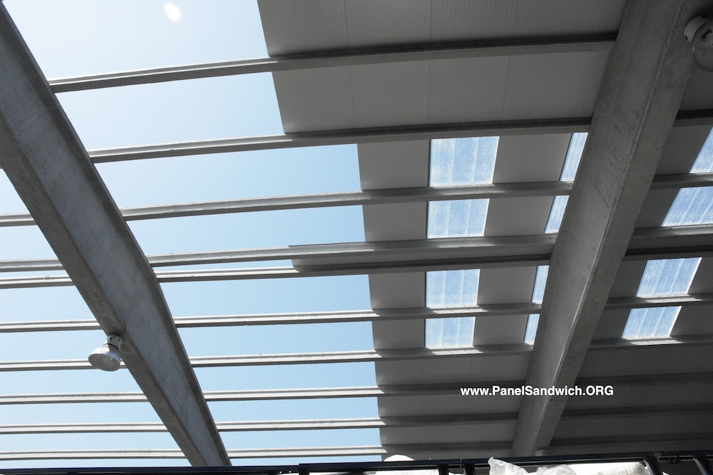
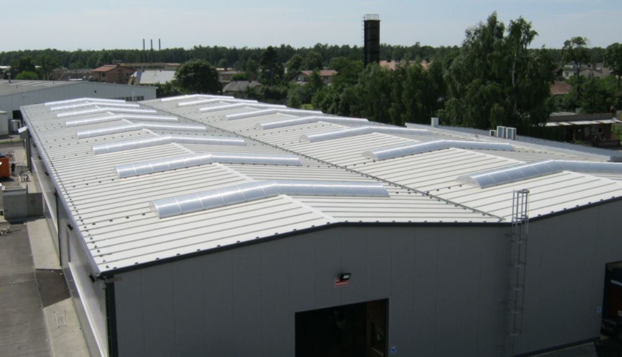
Roof Profiling
The ribs are formed during the profiling of the faces and provide geometry to the finished product.
Panel Continuity
Production’s dimensional precision facilitates alignment, overlap, and continuity on site.
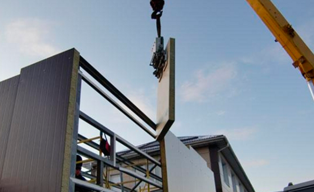
From Package to Site
Cutting to length and packaging must facilitate transport, lifting, and placement without damaging the faces.
Coils, profiling, preheating, and double-belt press
For large volumes, the original page describes automatic continuous foaming lines. The two sheets are unwound from coils and pass through rollers that generate the surface profile and panel edges.
They are then preheated to approximately 40°C, a historical datum associated in the source with optimal foam adhesion. The reactive mixture generated by the high-pressure equipment is deposited by an oscillating movement onto the lower face before entering the double-belt press.
Double-belt press
The press functions as a moving mold: it resists foam pressures during hardening and maintains the two faces at the necessary distance. In this section the foam also adheres to the upper profiled face.
The source highlights the high adhesive capacity of PUR/PIR on the surfaces with which they come into contact. Upon leaving the press, the core has already hardened sufficiently to cut the panel to size.
Cutting, stacking, and packaging
Cutting
The hardened continuous panel is cut to the necessary length with a saw. The original page mentions a band saw as a reference for the line described.
Stacking
Each panel passes to a stacking machine. In heavily profiled roof panels, the source describes an alternating arrangement to optimize package height: outer faces facing each other on one side and inner faces facing each other on the other.
Packaging
The package is protected with stretch polyethylene film, applied by a ring-shaped rotating wrapper.
Historical production line parameters
The source directly relates line speed to final thickness: the greater the thickness, the more time the panel needs in the double-belt press to complete adhesion and, therefore, the lower the speed must be.
| Parameter from the original page | Value | How it should be interpreted |
|---|---|---|
| Face preheating | ≈40°C | Reference from the line described; not a universal value. |
| Average speed cited | 6 m/min | Historical example of installation speed. |
| General speed range | 2–15 m/min | The source indicates that it decreases as thickness increases due to longer dwell time in press. |
| Capacity cited | ≈500,000 m² in one shift | Figure reproduced from historical content. Must be verified for any actual installation and is not presented as universal capacity. |
| Batch molding | ≈40 min in mold | Historical time of the system described. |
Production of panels with mineral wool
When the core is mineral wool—or another rigid material in the systems described—the original page indicates that the general line concept is maintained, but the core preparation and the method of bonding to the faces change.
Cutting into strips
One solution consists of cutting the slab into strips at right angles to the fiber orientation. The width of each strip matches the desired panel thickness.
90° rotation
The strips are rotated 90 degrees so that the fibers are oriented approximately normal to the outer faces. The source links this arrangement with the final compression and tensile properties of the composite panel.
Use of complete slab
The page also mentions, as a technique under development at the time of writing, the use of the complete mineral wool slab. That phrase is preserved as a historical reference and is not presented as a current innovation.
Staggering of strips
The joints between strips are arranged staggered to prevent all cutting planes from coinciding in the same cross section, since that coincidence could significantly deteriorate the shear strength of the assembly.
Adhesives for bonding the mineral core to the faces
The bond between the mineral wool strips and the metal faces is made with an adhesive suitable for the composition of the materials and the manufacturing process.
The adhesion phase is completed during the panel’s passage through the double-belt press.
| Type of adhesive cited | Application / curing | Advantage described | Limitation described |
|---|---|---|---|
| Solvent-based | Sprayed on both surfaces; curing can be accelerated with slight pressure and temperature. | Simple handling and good adhesion characteristics. | Once the layers are bonded, the relative position cannot be corrected. |
| Epoxy or polyurethane resin, 2 components | Components mixed in situ; after a preset time they react and harden rapidly. | Allows correction of layer position before hardening. | The layers must be kept under pressure for a specified period. |
Mineral Wool Panels: Process Result
In mineral wool panels, the core’s orientation and its bonding to the faces are especially relevant for the final performance.
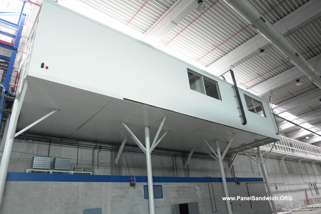
Mineral Wool Panel
The finished product must maintain joint continuity and dimensional stability.
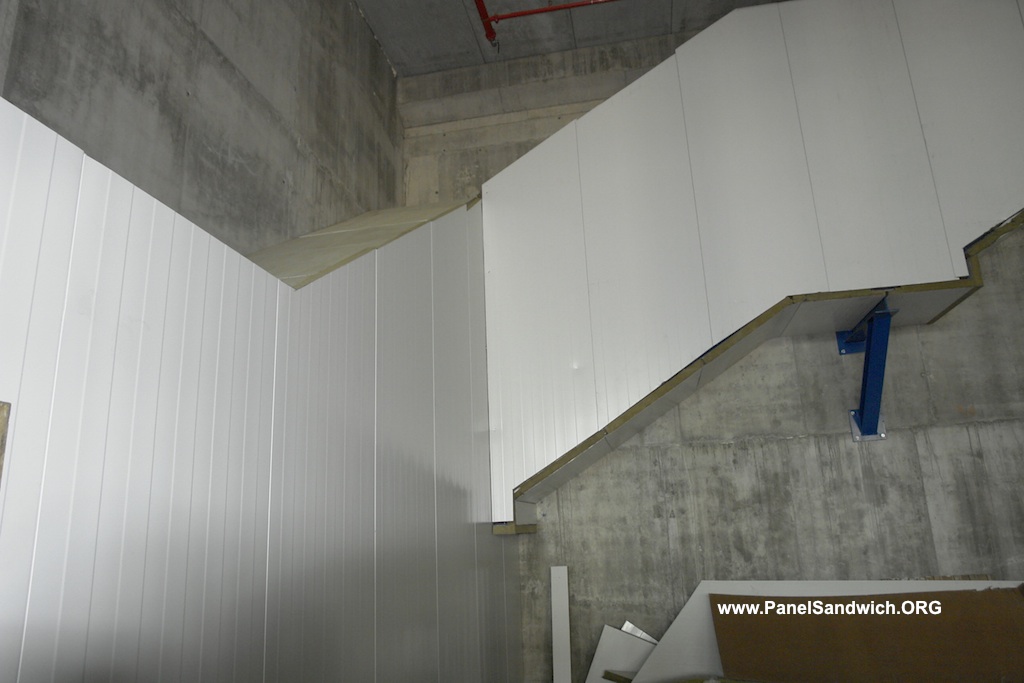
Junctions and Cuts
The produced geometry must allow for resolving system junctions, openings, and finishes.
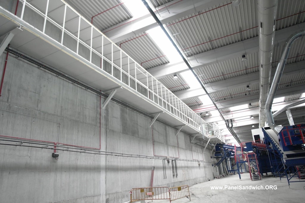
Result on Large Surfaces
The repeatability of width, thickness, and joint becomes visible in long enclosures.
What actually controls repeatable production
Chemical dosing
- Ratio between components
- Temperature and viscosity
- Pump flow rate
- Recirculation and injection
Geometry
- Face profiling
- Press separation
- Thickness
- Edge / joint details
Adhesion and core
- Uniform distribution
- Sufficient curing
- Strip orientation
- Core continuity
Finished product
- Cutting length
- Surface appearance
- Stacking / protection
- Traceability and defined controls
This page explains the manufacturing principle. Acceptance criteria, tolerances, and product performance must be consulted in the technical documentation and quality control applicable to the specific panel.
From process to finished product

Product geometry
The line must maintain thickness, face profile, and joint configuration in a repeatable manner.

Mineral wool core
The orientation and arrangement of the strips is part of the production process of the mineral panel.

From packaging to site
Stacking and final protection must allow the panel to be transported without damaging faces, edges, or joints.
Continue with the technical guide
After understanding production, it is advisable to review coatings, quality control, handling, and performance of the finished panel.
Frequently asked questions about sandwich panel manufacturing
The original page uses the term reaction injection molding for the high-pressure mixing and injection system of polyol, polyisocyanate, and additives. The components are dosed, recirculated, and mixed in a head before forming the foam.
In the batch system each panel is formed inside a closed mold. In the continuous system, the metal faces advance from coils through profiling, preheating, foaming, double-belt press, cutting, and stacking.
The historical source cites an approximate preheating of 40°C to favor adhesion. It should not be taken as a universal setpoint: the actual temperature depends on the formulation and the line.
According to the original content, a thicker panel needs to remain longer inside the press to adequately complete curing and adhesion of the core to the faces.
One technique described cuts the slab into strips, rotates them 90°, and arranges them staggered. They are then adhered to the metal faces and the assembly passes through the press.
No. They are historical references from the original source. The actual capacity of a line depends on width, thickness, formulation, shift duration, stops, and equipment configuration.